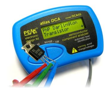

The voltage between the collector and the base should be higher than the voltage between the emitter and the base. Another way is to measure the voltage between the collector and the base, and between the emitter and the base. If the transistor is good, the resistance should be low.

One way is to use an ohmmeter to measure the resistance between the collector and the emitter. There are a few ways to test a transistor on an amp.

Transistors are frequently unable to operate normally for a period of time rather than over time. To begin, a positive lead from the meter should be connected to the collector terminal. The transistor’s base terminal and positive lead must be connected. To test a transistor’s functionality, you must connect it to the diode setting on your multi-meter. Make a list of the type of transistor, its location, and the identity of its terminal. A diode test function is typically included with digital multi-meters and can be used to test a transistor. If either of these values is outside of the expected range, the transistor is likely defective and should be replaced.Īn electronic transistor can be used within a circuit to create a switch or amplifier. This value should be in the range of 10 to 20 volts. Next, measure the voltage between the drain and source terminals. This value should be in the range of 0.5 to 1.5 volts. Then, using a multimeter set to the voltage (AC or DC) setting, measure the voltage between the gate and source terminals. To do this, first identify the gate, source, and drain terminals. The most common way to test a FET is to measure the gate-source and drain-source voltages. However, they are also more difficult to test. FETs are typically more robust than BJTs and can handle higher voltages and currents. FETs are used in the power amp section of the amplifier, and are responsible for providing the final amplification of the signal before it is sent to the speakers. If any of these values are outside of the expected range, the transistor is likely defective and should be replaced. This value should be somewhere in between the collector-emitter and base- emitter resistance values. Finally, measure the resistance between the collector and base terminals. This value should be much higher than the collector-emitter resistance, typically in the range of several hundred ohms. Next, measure the resistance between the base and emitter terminals. This should be a low resistance value, typically in the range of a few ohms. Then, using a multimeter set to the resistance (ohms) setting, measure the resistance between the collector and emitter terminals. To test a BJT, first identify the collector, base, and emitter terminals. They are responsible for amplifying the signal from the guitar’s pickups, and can be found in the preamp and power amp sections of the amplifier. BJTs are the most common type of transistor used in guitar amplifiers.

Each type of transistor has its own unique set of characteristics, and thus its own set of tests that need to be performed in order to determine if it is functioning properly. There are two main types of transistors used in guitar amplifiers: bipolar junction transistors (BJTs) and field-effect transistors (FETs). First experimental tests on the prototypes show the correct operations of the device as demonstrated from the changing of the output characteristic from triode-like to pentode-like behaviors, which are ascribed to the two main operation principles of the device.When testing a transistor in a guitar amplifier, it is important to first identify the type of transistor being used. In order to avoid the reduction of carrier lifetime into the channel due to ion implantation and trench etching, an ad-hoc fabrication process has been set-up to enable the conductivity modulation into the channel. The structure is based by two p +-type regions symmetrically placed at both sides of a n-type region channel and the device implements two control mechanisms: into the channel the potential barrier controls the electron flow in the off-state operations, like VJFET-based devices, whereas, during the on-state, the holes injected from the p-n junctions induce the conductivity modulation of the channel reducing the on-resistance with beneficial effects on current gain and switching operations. In this paper the Bipolar Mode Field Effect Transistor (BMFET) is demonstrated for the first time in 4H-SiC.


 0 kommentar(er)
